


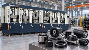
Rubber-to-metal bonded parts combine the elasticity, sealing performance or vibration control of rubber with the structural strength of metal. Typical products include suspension bushings, engine mounts, anti-vibration pads, bonded seals, rubber rollers, metal-core wheels and industrial damping components.
Producing these parts requires more than filling a mold with rubber. Metal inserts must be prepared, positioned and held securely while plasticized compound flows around them. Bonding agents, injection pressure, mold temperature, curing conditions and air removal all influence the final interface between rubber and metal.
A properly configured rubber injection molding machine provides controlled feeding, repeatable shot preparation and programmable injection profiles for insert-molded products. The machine, mold, compound, metal insert and bonding process must still be evaluated as one manufacturing system.
What Are Rubber-to-Metal Bonded Parts?
Rubber-to-metal bonded parts are molded components in which vulcanized rubber is permanently attached to a steel, aluminum or other compatible metal insert.
The metal normally provides:
- Structural support
- Mounting points
- Load transfer
- Dimensional stability
- Wear resistance
- Mechanical connection
The rubber section may provide:
- Vibration isolation
- Impact absorption
- Flexible movement
- Noise reduction
- Sealing
- Electrical isolation
- Surface protection
- Controlled compression
During molding, rubber flows into the space around or between prepared inserts. Heat and pressure vulcanize the compound while the bonding system creates adhesion at the rubber-metal interface.
The process differs from assembling a cured rubber component with a metal part afterward. Injection molding forms and bonds the rubber during the same production cycle.
Common Rubber-to-Metal Injection-Molded Products
Suspension Bushings
Suspension bushings typically contain inner and outer metal sleeves connected by a molded rubber layer. The rubber permits controlled movement while isolating vibration and noise.
Production challenges include:
- Maintaining concentricity between metal sleeves
- Preventing insert movement during injection
- Filling narrow annular spaces
- Controlling rubber thickness
- Avoiding trapped air
- Achieving uniform bonding around the complete insert
Fixture and mold design are critical because small insert-position changes can alter rubber thickness and product performance.
Engine and Equipment Mounts
Rubber mounts support engines, motors, pumps, compressors and industrial equipment while reducing transmitted vibration.
These products may contain:
- Threaded studs
- Steel plates
- Embedded nuts
- Internal sleeves
- Multiple bonded inserts
- Thick rubber sections
- Voids or tuned geometric features
Thick sections and multiple inserts create complex flow paths. Vacuum assistance and staged injection may be required to help rubber reach distant areas without trapping air.
Anti-Vibration Pads
Bonded anti-vibration pads commonly combine a rubber block with one or two metal plates. Bolt holes, studs or threaded inserts connect the product to machinery or supporting structures.
Reliable production requires consistent insert placement and controlled flash around the metal edges.
Rubber Bonded Bushings
Industrial bushings are used in machinery, vehicles, agricultural equipment and suspension assemblies. Some designs contain one metal sleeve, while others place rubber between concentric inner and outer tubes.
Material distribution must remain uniform around the sleeve. An off-center insert can create uneven stiffness and premature product failure.
Bonded Seals
Bonded seals integrate rubber with a metal washer, ring, plate or reinforcing structure.
The metal supports the component, while rubber creates the functional sealing area. Critical production requirements include:
- Accurate sealing geometry
- Low flash
- Consistent rubber coverage
- Clean metal surfaces
- Stable rubber-metal adhesion
- Controlled compression thickness
Rubber Rollers
Rubber rollers contain a metal shaft or cylindrical core covered with molded rubber. They are used in conveying, printing, material handling and industrial equipment.
Long products may require special runner layouts and clamping structures to distribute rubber evenly along the core.
Metal-Core Wheels
Industrial wheels and rollers may use a steel or aluminum core bonded to an outer rubber layer. The interface must withstand repeated load, deformation and rotation.
TASU’s guide to rubber injection molding machines for solid tires and industrial wheels explains additional requirements for thick rubber sections and metal cores.
Rubber-Coated Components
Injection molding can also cover selected areas of a metal product with rubber for gripping, cushioning, sealing or protection.
Examples include:
- Rubber-coated brackets
- Metal handles
- Cable-support parts
- Protective stops
- Equipment feet
- Rubber-coated fasteners
- Reinforced connectors
Masking and mold design must prevent rubber from reaching metal surfaces that need to remain exposed.
Where Rubber-to-Metal Parts Are Used
| Industry | Typical products | Main function |
|---|---|---|
| Automotive | Bushings, engine mounts, suspension parts and bonded seals | Vibration control, movement and sealing |
| Industrial machinery | Equipment mounts, rollers, stops and couplings | Impact absorption and noise reduction |
| Rail transportation | Suspension components, bump stops and isolation mounts | Load transfer and vibration isolation |
| Construction equipment | Heavy-duty bushings, mounts and protective components | Shock and vibration resistance |
| Pumps and compressors | Mounts, diaphragms and bonded sealing parts | Vibration reduction and sealing |
| HVAC equipment | Compressor mounts and isolation pads | Noise and vibration control |
| Agricultural machinery | Bushings, rollers and damping parts | Impact resistance and flexible movement |
| Electrical equipment | Insulating mounts and protective bonded parts | Isolation and mechanical protection |
Product requirements differ significantly between industries. The correct compound, metal, adhesive system and molding process must be selected according to the operating load, temperature, chemical exposure and service environment.
How the Rubber-to-Metal Injection Molding Process Works
1. Metal Insert Manufacturing
Metal inserts are produced according to the required dimensions and tolerances. Processes may include stamping, casting, machining, forming or welding.
The insert should be inspected for:
- Dimensions
- Concentricity
- Surface defects
- Burrs
- Oil contamination
- Rust
- Welding residue
- Sharp edges
- Deformation
Dimensional variation in the insert can affect mold loading, rubber thickness and final product geometry.
2. Surface Preparation
Metal surfaces must be prepared before applying a bonding agent. Oil, oxidation, dust or other contaminants can prevent reliable adhesion.
Preparation methods vary according to the metal and bonding system. They may include:
- Degreasing
- Cleaning
- Abrasive blasting
- Chemical treatment
- Drying
- Surface activation
The validated procedure should be followed consistently. Over-cleaning, incomplete drying or contamination after preparation may reduce bond quality.
3. Bonding-Agent Application
A compatible bonding system is applied to the metal areas that will contact the rubber.
Application may be completed by:
- Spraying
- Brushing
- Dipping
- Rolling
- Automated dispensing
Coating thickness and coverage should remain consistent. Excess material can create buildup, while incomplete coverage may leave unbonded areas.
Prepared inserts must be stored under controlled conditions and used within the validated processing period.
4. Insert Loading
Operators or robots position the metal inserts inside the mold.
The mold may use:
- Location pins
- Magnetic holders
- Mechanical clips
- Spring-loaded fixtures
- Shaped pockets
- Threaded supports
- Replaceable insert nests
Each insert must remain in the correct position during mold closing, vacuuming and injection.
5. Mold Closing and Vacuuming
After insert loading, the mold closes and establishes the required clamping condition.
Vacuum may then remove air from the cavity. Rubber-to-metal products often contain narrow spaces around inserts where displaced air can become trapped.
The guide to vacuum rubber molding machines explains how mold sealing, evacuation time and vacuum level affect cavity filling.
6. Rubber Injection
Prepared compound is injected through the nozzle, runner and gate into the mold cavity.
The injection profile must fill the product without:
- Moving the insert
- Washing away the bonding agent
- Folding thin metal sections
- Trapping air behind the insert
- Creating weld-line weakness
- Producing excessive flash
Multi-stage injection speed is often useful. The machine can reduce speed as material approaches sensitive inserts or end-of-fill areas.
7. Vulcanization and Bond Formation
Heat and pressure vulcanize the rubber inside the mold. The bonding system reacts under the validated molding conditions and connects the cured rubber to the prepared metal surface.
Time and temperature must be sufficient for both rubber curing and bond formation. Under-curing can weaken the rubber or interface, while unnecessary over-curing reduces production efficiency and may affect product properties.
8. Mold Opening and Part Removal
After vulcanization, the mold opens and the bonded component is removed.
Demolding must not apply excessive force to:
- Thin rubber edges
- Bonded interfaces
- Metal studs
- Flexible sections
- Sealing lips
Robotic removal can improve consistency when product shape and mold structure support reliable gripping.
9. Inspection and Testing
Finished parts are checked for dimensions, appearance, bond coverage and product-specific performance.
Test requirements depend on the application and customer specification.
Why Injection Molding Is Used for Rubber-to-Metal Parts
Controlled Material Distribution
Injection pressure moves plasticized rubber through narrow spaces and around complex inserts. Proper runner and gate design can provide more uniform filling than manually placing multiple rubber preforms.
Repeatable Shot Preparation
Automatic feeding, plasticization and metering help maintain consistent compound conditions between cycles.
Stable shot weight is important for products with controlled rubber thickness or multiple cavities.
Support for Complex Insert Geometry
Injection molding can form rubber around sleeves, studs, plates, washers and other embedded structures.
Complex geometry still requires suitable flow paths and secure insert fixtures.
Multi-Cavity Production
Small bonded seals, bushings and mounting parts may be produced in multi-cavity molds. Balanced runners and repeatable insert placement are essential for cavity-to-cavity consistency.
Automation Potential
Insert loading, bonding-agent application, molding, demolding and inspection can be partially or fully automated.
The appropriate automation level depends on:
- Insert geometry
- Product size
- Cycle time
- Cavity count
- Production volume
- Required orientation
- Bonding-agent process
- Inspection requirements
Reduced Dependence on Manual Preforming
Injection molding meters and delivers the compound automatically. This can reduce variation caused by manually weighed and positioned preforms.
Machine Requirements for Rubber-to-Metal Molding
Stable Injection Pressure
The machine must provide enough pressure to move rubber around the inserts and into narrow cavity sections.
Pressure should remain controllable rather than simply high. Excessive pressure can move inserts, increase flash or force rubber into unwanted areas.
Multi-Stage Injection Speed
Programmable speed stages allow the process to respond to different sections of the cavity.
A typical profile may use:
- Controlled speed through the nozzle and runner
- Faster filling across the main rubber section
- Reduced speed around sensitive inserts
- Slower final filling to release air
The actual stages should follow short-shot testing and observed material flow.
More information is available in the rubber injection molding pressure and speed guide.
Accurate Shot Metering
Insufficient material can leave exposed metal or incomplete rubber sections. Excessive material increases flash and mold contamination.
Shot volume should account for:
- Rubber product volume
- Runner volume
- Number of cavities
- Process cushion
- Compound density
Secure Clamping
Injection pressure acts across the projected area of the molded part and runner system. Clamping force must keep the mold closed throughout filling and vulcanization.
Poor mold closure may create flash along the product edge or around the metal insert.
Stable Plasticization
Changes in compound condition affect flow, pressure and bonding-agent contact.
Controlled feeding and FIFO material movement help maintain more predictable residence time. The rubber injection molding machine feeding system explains how feeding and plasticization influence shot stability.
Uniform Mold Temperature
Temperature differences can produce uneven filling, curing and bond development.
The heating system should maintain stable temperatures around all cavities and inserts. Large metal parts can absorb heat and temporarily change local mold conditions, especially after production starts or resumes.
Vacuum and Exhaust Control
Metal inserts divide the cavity and create additional air-trap locations. Vacuum capability and properly positioned vents help remove air before it becomes enclosed by the advancing rubber.
Suitable Mold Access
Insert loading requires enough access for an operator or robot to position the metal components safely and accurately.
Machine structure should be selected according to:
- Insert-loading direction
- Mold-opening direction
- Product removal path
- Insert weight
- Robot access
- Factory layout
Process Monitoring
Recording injection pressure, filling time, mold temperature and curing time can help identify gradual variation.
Pressure-curve changes may indicate:
- Insert-position problems
- Gate restriction
- Compound viscosity variation
- Blocked vents
- Shot-volume changes
- Premature curing
Vertical vs. Horizontal Machines for Insert Molding
| Consideration | Vertical configuration | Horizontal configuration |
|---|---|---|
| Insert placement | Convenient access to an upward-facing mold | Depends on mold and loading direction |
| Insert stability | Gravity can help retain some inserts | Fixtures may be required to prevent movement |
| Automation access | Suitable for rotary tables and insert-loading robots | Suitable for inline automation and conveyors |
| Product removal | Often removed upward | Commonly removed horizontally or downward |
| Mold structure | Useful for many insert-molding applications | Suitable for specific long, large or automated products |
| Factory layout | Smaller floor area in some configurations | Easier integration with linear production lines in some cases |
Machine orientation should not be selected by product name alone. Insert geometry, mold structure, automation and demolding direction are more important.
TASU also supplies horizontal rubber injection molding machines for industrial rubber products and automated production configurations.
Mold Design Considerations
Insert Location and Retention
The mold must hold every insert in a repeatable position.
Fixtures should prevent movement without damaging the metal surface or interfering with rubber flow.
Critical questions include:
- Can the insert shift during mold closing?
- Can injection pressure rotate or lift it?
- Is incorrect loading physically possible?
- Can the operator confirm orientation?
- Can the insert be removed after molding?
- Are fixtures replaceable when worn?
Gate Position
Gate location determines how rubber approaches the metal insert.
Poor gate placement may cause:
- Insert movement
- Uneven rubber thickness
- Bonding-agent displacement
- Air entrapment
- Visible flow lines
- Weak weld areas
- Excessive pressure loss
The gate should not direct an uncontrolled high-speed flow toward a thin insert or coated surface.
Runner Balance
Multi-cavity molds need balanced flow paths so each cavity receives similar material volume and pressure.
Variations between cavities may result from:
- Different runner lengths
- Unequal gate dimensions
- Temperature differences
- Insert-position variation
- Blocked vents
- Inconsistent bonding-agent buildup
Vent Position
Air commonly becomes trapped behind inserts or where two rubber flow fronts reconnect.
Vents should be considered near:
- End-of-fill areas
- Insert edges
- Deep pockets
- Blind sections
- Flow-front junctions
- Thin rubber sections
The rubber mold venting guide covers vent locations, air-trap symptoms and maintenance requirements.
Metal Thermal Expansion
Metal inserts heat inside the mold and may expand during curing. Tool designers should consider insert dimensions, mold fit and removal conditions at operating temperature.
Bonding-Agent Clearance
Mold location surfaces should avoid unnecessarily scraping prepared bonding areas during loading.
Accumulated bonding agent can also contaminate fixtures and change insert position. Cleaning access should be included in the mold design.
Demolding
The bonded interface may be exposed to stress during product removal. Ejectors and gripping points should apply force to structurally suitable areas.
Rubber and Metal Preparation Requirements
Rubber Compound Selection
The compound is chosen according to the required:
- Hardness
- Elasticity
- Temperature resistance
- Oil resistance
- Chemical resistance
- Weather resistance
- Compression behavior
- Fatigue performance
- Bonding compatibility
Common rubber families include EPDM, NBR, natural rubber, CR, HNBR and FKM. The complete formulation—not only the rubber family—affects injection behavior and adhesion.
Metal Selection
Frequently used inserts include carbon steel, stainless steel and aluminum. Surface condition and bonding preparation differ by metal type.
The metal should be compatible with:
- Service environment
- Mechanical load
- Surface-treatment process
- Bonding system
- Mold temperature
- Required corrosion resistance
Insert Storage
Prepared inserts should be protected against dust, oil, moisture and unnecessary handling.
Storage controls may include:
- Covered containers
- Defined shelf life
- Batch identification
- Temperature and humidity limits
- First-in, first-out use
- Gloves for manual loading
Common Rubber-to-Metal Molding Defects
| Defect | Possible causes | Recommended checks |
|---|---|---|
| Rubber separates from metal | Contamination, unsuitable bonding agent or incorrect cure | Review cleaning, coating and vulcanization |
| Partial bonding | Incomplete coating or trapped air | Inspect bonding coverage, vents and vacuum |
| Insert movement | Excessive filling speed or weak fixture | Reduce local speed and improve retention |
| Exposed metal area | Short shot, air trap or incorrect insert position | Check shot volume, venting and loading |
| Flash around insert | Excessive pressure, worn fixture or poor mold fit | Inspect pressure, location components and mold surfaces |
| Rubber thickness variation | Off-center insert or unstable loading | Check fixture wear and insert dimensions |
| Burn mark behind insert | Compressed air or blocked vent | Clean vents and optimize final filling speed |
| Bonding-agent buildup | Excessive coating or poor application control | Review coating thickness and mold cleaning |
| Blisters or bubbles | Moisture, trapped gas or unsuitable cure | Check insert drying, compound and vacuum |
| Insert deformation | Excessive pressure or insufficient insert support | Review injection profile and fixture design |
| Rubber tearing during demolding | Under-curing or unsuitable ejection | Check cure conditions and removal method |
| Cavity-to-cavity variation | Runner imbalance, insert variation or uneven temperature | Compare each cavity and process condition |
Visible separation is not the only possible bonding problem. Weak adhesion may exist below the surface, so functional testing should follow the product specification.
Quality Control for Rubber Bonded Metal Parts
Incoming Metal Inspection
Inspect metal components before preparation and molding.
Useful checks include:
- Critical dimensions
- Surface condition
- Concentricity
- Flatness
- Thread quality
- Weld condition
- Coating or plating condition
- Part cleanliness
Bonding-Process Control
Production records should identify:
- Cleaning batch
- Surface-treatment process
- Bonding-agent batch
- Application time
- Drying conditions
- Insert storage duration
- Operator or automated line
- Mold and cavity number
Finished Product Inspection
Common checks include:
- Overall dimensions
- Rubber thickness
- Insert position
- Concentricity
- Flash
- Surface defects
- Exposed metal
- Voids
- Bond coverage
- Product weight
- Hardness
Bond Strength Testing
The applicable test method depends on product design and customer requirements.
Possible evaluations include:
- Pull testing
- Peel testing
- Shear testing
- Torque testing
- Destructive sectioning
- Fatigue testing
- Compression testing
- Load-deflection testing
Test values should be based on the approved product specification rather than a general target applied to every bonded component.
Process Data Review
Useful molding records include:
- Injection pressure
- Injection time
- Actual filling speed
- Shot volume
- Plasticizing time
- Mold temperature
- Vacuum level
- Cure time
- Product weight
- Rejection reason
Linking quality results with machine data helps distinguish a molding issue from an insert-preparation or bonding-agent problem.
Cold Runner Systems for Bonded Parts
Conventional runner material cures together with the molded product and must be removed after every cycle.
Cold runner technology keeps the compound inside the runner below its vulcanization condition. This can reduce cured runner waste, particularly when:
- Compound cost is high
- Runner weight is significant
- Production volume is large
- The mold contains multiple cavities
- Runner removal requires additional labor
Cold runner systems require accurate temperature control and suitable insulation between the runner and heated mold.
Economic evaluation should compare the material saved against tooling cost, maintenance and process complexity.
Automation Options
Automatic Insert Loading
Robots can pick, orient and place metal inserts into the mold. Repeatable insert geometry and reliable feeding are necessary for stable automation.
Presence and Position Detection
Sensors or vision systems can confirm whether inserts are present and correctly positioned before mold closing.
This helps prevent:
- Empty cavities
- Double-loaded inserts
- Incorrect orientation
- Mold damage
- Unbonded products
Automated Bonding-Agent Application
Controlled spraying or dispensing can improve coating consistency and reduce manual handling. The system must still manage cleaning, drying and overspray.
Automatic Demolding
Robots can remove finished parts and place them on cooling fixtures, conveyors or inspection stations.
Grippers should avoid pulling directly against a sensitive bonded interface.
In-Line Inspection
Production lines may integrate:
- Vision inspection
- Product weighing
- Insert-presence checking
- Dimensional measurement
- Metal detection
- Marking
- Traceability systems
Automation should address an identified production need rather than add unnecessary complexity.
Information Needed to Configure the Machine
Manufacturers should provide the following information before equipment selection:
- Finished product drawing
- 3D product data when available
- Rubber compound type
- Rubber hardness
- Part weight
- Total shot volume
- Metal insert drawing
- Metal type
- Insert weight
- Number of inserts per product
- Number of mold cavities
- Mold dimensions
- Projected molding area
- Bonding-agent process
- Vulcanization time
- Required production output
- Current molding defects
- Insert-loading method
- Demolding method
- Automation requirements
- Quality and testing standards
Actual inserts, rubber samples and existing molds may also be needed for process evaluation.
TASU’s rubber injection molding solutions combine equipment, feeding, injection, vacuum, cold runner design and mold-process development for industrial rubber products.
Frequently Asked Questions
Can a rubber injection molding machine mold rubber directly onto metal?
Yes. Prepared metal inserts are placed inside the mold before rubber is injected and vulcanized around them.
What products can be made through rubber-to-metal injection molding?
Common products include bushings, engine mounts, anti-vibration pads, bonded seals, rollers, couplings, equipment feet and metal-core wheels.
Why does rubber separate from the metal insert?
Common causes include oil or oxidation on the metal, unsuitable surface preparation, incomplete bonding-agent coverage, contamination after coating and incorrect vulcanization conditions.
Can injection pressure move the metal insert?
Yes. High flow speed or insufficient fixture support can shift, rotate or deform the insert during filling.
Is vacuum required for rubber-to-metal molding?
Not every product requires vacuum. Parts with complex inserts, deep cavities or enclosed flow paths are more likely to benefit from vacuum-assisted air removal.
Which rubber compounds can bond to metal?
EPDM, NBR, natural rubber, CR, HNBR, FKM and other compounds may be used. Compatibility depends on the complete rubber formulation, metal preparation and bonding system.
Should the bonding agent be applied manually or automatically?
Both methods are possible. The correct choice depends on insert geometry, coating requirements, production volume and consistency targets.
How can cavity-to-cavity bonding variation be reduced?
Check runner balance, mold temperature, venting, insert dimensions, coating consistency and insert positioning in every cavity.
Can existing compression molds be used on an injection machine?
Some molds may be adapted, while others require changes to runners, gates, vents or insert-retention structures. The mold should be evaluated before machine selection.
Which machine orientation is best for metal inserts?
Vertical machines often make manual insert placement convenient, while horizontal machines can integrate effectively with specific automated lines. Mold structure and loading direction should determine the choice.
Can cold runners be used for rubber-to-metal products?
Yes, when the compound and mold design are suitable. Cold runners can reduce cured runner waste in high-volume production.
What information is required for a machine quotation?
Provide product and insert drawings, rubber type, part weight, cavity count, mold size, cure time, production target and required automation level.
Conclusion
Rubber-to-metal injection molding combines compound preparation, metal treatment, insert positioning, mold filling, vulcanization and bond formation in one controlled production system. Reliable parts depend on clean metal surfaces, consistent bonding-agent application, secure insert fixtures, balanced rubber flow and stable curing conditions.
TASU manufactures fully automatic rubber injection molding machines for bushings, anti-vibration mounts, bonded seals, industrial rollers and other rubber-to-metal products. To evaluate your inserts, mold structure, compound and production requirements, contact TASU.