


Composite insulators combine an insulating core, metal end fittings and a molded silicone rubber housing. Their long sheds, narrow interfaces and extended flow paths require stable material preparation, controlled injection and reliable air removal.
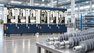
A dedicated rubber injection molding machine for composite insulators injects prepared HTV silicone rubber around the FRP rod and associated components. The machine must distribute the compound evenly across the insulator profile without leaving voids, incomplete sheds or weak areas around the core.
Successful production depends on more than injection pressure. Compound condition, FRP rod preparation, mold alignment, gate position, vacuum level, temperature distribution and vulcanization time must be controlled together.
TASU develops rubber injection molding machines with programmable feeding, vacuum, injection and curing controls for composite insulators and other technical rubber products.
What Is a Composite Insulator?
A composite insulator—also called a polymer insulator—uses different materials to perform electrical, mechanical and environmental functions.
Its main components normally include:
- FRP core rod
- Silicone rubber housing
- Silicone rubber sheds
- Metal end fittings
- Sealing or interface structures
The FRP rod carries the mechanical load. Metal fittings connect the insulator to the electrical system, while the molded silicone rubber housing protects the core and forms the required creepage profile.
Silicone rubber is commonly selected for the external housing because it can provide electrical insulation, weather resistance and flexibility. Exact compound properties depend on the formulation and the required product standard.
Composite Insulators Produced by Rubber Injection Molding
Rubber injection equipment may be configured for several composite-insulator designs.
Suspension Insulators
Suspension insulators are used on overhead transmission and distribution lines. Their extended rod structure and repeated sheds require uniform rubber coverage along the core.
Tension Insulators
Tension insulators carry mechanical loads where conductors change direction or terminate. Bonding and sealing around the end-fitting interfaces require particular attention.
Line Post Insulators
Line post designs support conductors in a fixed position. Product dimensions, shed arrangement and mounting structures vary according to voltage level and system design.
Station Post Insulators
Station post insulators are used in substations and electrical equipment. Larger product dimensions may require increased shot volume, longer molds and specialized handling systems.
Railway Insulators
Railway electrification systems use composite insulators with application-specific dimensions and mounting structures. Production equipment must match the product length, mold configuration and required output.
Surge Arrester Housings
Silicone rubber housings can also be molded around surge-arrester cores or assemblies. Internal components must remain correctly positioned during mold closing and injection.
Insulating Rods and Electrical Components
The same molding principles may be applied to silicone-covered rods, electrical connectors and other composite insulation components.
Why Injection Molding Is Used for Composite Insulators
Uniform Silicone Rubber Coverage
Injection pressure moves prepared silicone rubber around the FRP rod and into the shed cavities. Controlled filling helps maintain consistent coverage across the product.
Formation of Complex Shed Profiles
Composite-insulator molds contain repeated sheds, thin edges and long flow paths. Injection molding can reproduce these details when gates, runners and vents are properly designed.
Repeatable Shot Preparation
Automatic feeding and metering provide more consistent material delivery than manually prepared charges.
Stable shot volume is important because insufficient material can leave incomplete sheds, while excessive material increases flash and mold contamination.
Controlled FRP Rod Encapsulation
The rubber housing should cover the intended rod surface without leaving exposed areas or internal voids.
Rod centering and mold alignment determine whether the silicone thickness remains consistent around the circumference.
Production Automation
Modern equipment can coordinate:
- Compound feeding
- Shot metering
- Mold closing
- Vacuuming
- Injection
- Vulcanization
- Mold opening
- Product removal
Automation reduces dependence on manual timing and supports repeatable production records.
Multi-Station Production
Long vulcanization periods can limit output when one injection unit serves only one mold. Multi-station equipment allows different molds to proceed through injection, curing, opening and unloading stages at the same time.
Actual production capacity depends on product size, shot volume, mold count, curing time and handling requirements.
HTV Silicone Rubber for Composite Insulator Molding
High-temperature-vulcanizing silicone rubber is commonly used for molded composite-insulator housings.
Unlike thermoplastic material, HTV silicone does not simply melt and then solidify. The compound is softened and plasticized before being injected into a heated mold, where it undergoes irreversible vulcanization.
Important compound characteristics include:
- Viscosity
- Scorch safety
- Cure behavior
- Flow properties
- Filler distribution
- Storage condition
- Batch consistency
- Required electrical properties
- Required mechanical properties
Machine settings must be established with the actual production compound. Different silicone formulations may require different barrel temperatures, screw speeds, injection profiles and curing conditions.
The guide to rubber plasticization in injection molding explains how feeding, shear, temperature and residence time affect compound condition.
Composite Insulator Manufacturing Process
1. FRP Rod Inspection
The core rod should be inspected before molding.
Checks may include:
- Diameter
- Straightness
- Surface condition
- Length
- Cleanliness
- Visible damage
- End preparation
- Compatibility with the mold fixture
A bent or dimensionally inconsistent rod can be difficult to center inside the mold.
2. End-Fitting Assembly
Metal end fittings are installed according to the approved product design and assembly process.
The assembly should be checked for:
- Overall length
- Alignment
- Concentricity
- Connection condition
- Surface cleanliness
- Position relative to the mold
The fitting structure must not interfere with mold closing or silicone flow.
3. Surface Preparation
The bonding areas of the FRP rod and related components are cleaned and prepared according to the validated manufacturing process.
Oil, dust, moisture and handling contamination can affect the interface between the silicone housing and the core.
Prepared rods should be protected from contamination before loading.
4. Core Positioning
The rod assembly is loaded into the mold and supported by dedicated positioning structures.
Fixtures must:
- Center the rod
- Prevent bending
- Control axial position
- Withstand injection forces
- Avoid damaging prepared surfaces
- Permit reliable demolding
Long products may require several support points to prevent deflection.
5. Mold Closing
The mold closes around the core assembly. Closing speed and force should be controlled to protect the rod, fittings and mold components.
Sensors or mechanical checks may be used to confirm correct product positioning before full clamping.
6. Vacuuming and Air Removal
Air remains inside every empty mold cavity. The FRP rod and repeated shed geometry create additional areas where air may become trapped.
Vacuum removes air before injection and helps the silicone rubber reach narrow sections around the core.
TASU’s vacuum rubber molding machine guide explains how mold sealing, evacuation time and vacuum level influence filling quality.
7. Silicone Rubber Injection
Plasticized HTV silicone rubber is injected through the runner and gate system.
Injection may use multiple pressure and speed stages to:
- Fill the main runner
- Distribute material along the product
- Form the shed cavities
- Protect the core position
- Reduce air compression near the end of filling
The correct profile depends on mold length, gate arrangement, shot volume and compound viscosity.
8. Vulcanization
Heat from the mold cures the silicone rubber around the core.
Temperature must remain sufficiently uniform throughout the mold. Cold areas may produce incomplete curing, while excessive local temperatures can cause premature curing during filling.
9. Mold Opening and Demolding
After vulcanization, the mold opens and the composite insulator is removed.
Long products need controlled support during removal to prevent bending, twisting or damage to thin shed edges.
10. Inspection and Testing
Finished products are inspected according to the manufacturer’s quality plan and applicable product requirements.
Inspection may include:
- Overall dimensions
- Shed geometry
- Surface condition
- Flash
- Exposed core areas
- Voids or bubbles
- Housing thickness
- Interface condition
- End-fitting alignment
Electrical and mechanical testing should follow the applicable customer specification or industry standard.
Machine Requirements for Composite Insulator Production
Sufficient Injection Capacity
Shot capacity must cover the silicone rubber housing, runner volume and required process allowance.
Machine selection should be based on actual molded volume rather than insulator length alone.
An oversized injection unit may increase material residence time. Insufficient capacity may require multiple injection stages or prevent complete filling.
Stable Injection Pressure
Long flow distances and repeated sheds generate substantial resistance. The injection system must maintain controlled material movement throughout the filling stage.
High maximum pressure alone does not guarantee good results. Nozzle, runner, gate and cavity restrictions must also be evaluated.
Programmable Injection Speed
Multi-stage speed control helps manage material flow through different parts of the mold.
A typical profile may use:
- Controlled runner filling
- Faster distribution through the main housing
- Reduced speed across thin shed sections
- Slower final filling to help air escape
Short-shot testing can reveal how silicone travels through the mold and where air becomes trapped.
The rubber injection molding pressure and speed guide provides a structured setup method.
Reliable Vacuum System
A composite insulator injection molding machine should coordinate mold closing, vacuuming and injection.
Important vacuum-system components include:
- Vacuum pump
- Vacuum tank
- Control valves
- Vacuum sensors
- Mold sealing components
- Connection hoses
- Programmable timing
- Leakage alarms
A larger pump cannot compensate for damaged seals or poorly designed evacuation channels.
Uniform Mold Heating
Long molds require consistent temperature distribution along the complete product.
Uneven heating can produce:
- Different cure rates
- Local viscosity variation
- Incomplete filling
- Surface inconsistency
- Difficult demolding
- Product deformation
Independent heating zones allow operators to monitor and adjust different sections of the mold.
Controlled Plasticization
HTV silicone must become sufficiently soft and uniform for injection without beginning substantial curing inside the barrel.
Important controls include:
- Feed dimensions
- Screw speed
- Barrel temperature
- Back pressure
- Plasticizing time
- Shot size
- Material residence time
FIFO feeding helps keep the material sequence more predictable during continuous production.
Stable Clamping Structure
The clamping system must keep the long mold securely closed during injection and vulcanization.
Insufficient clamping or uneven mold support can produce:
- Flash
- Mold separation
- Inconsistent shed thickness
- Core displacement
- Premature mold wear
Clamping force should be evaluated together with projected cavity area, runner area and injection pressure.
Long-Mold Support and Alignment
Composite-insulator molds may be longer than molds used for small rubber components. Machine platens and mold-support structures must maintain alignment throughout repeated heating and clamping cycles.
Multi-Station Coordination
A mobile injection unit may serve several mold stations. While one mold is being injected, other stations can continue vulcanization, opening or unloading.
This configuration can improve equipment utilization when curing time is much longer than injection time.
TASU’s rubber product injection molding systems include multi-station configurations for different molded rubber products.
Mold Design for Composite Insulators
Runner Layout
Runner design determines how silicone reaches different areas of the long cavity.
The system should minimize excessive pressure loss while distributing material predictably across the product.
Gate Position
Gate position influences:
- Filling direction
- Weld-line location
- Air movement
- Pressure distribution
- Core loading
- Gate-removal work
- Surface appearance
Poor gate placement may direct excessive material force against the FRP rod or trap air at distant shed sections.
Cavity Alignment
Upper and lower mold sections must align accurately to maintain consistent housing and shed geometry.
Alignment components should be inspected for wear as part of preventive maintenance.
Rod-Centering Structure
The centering system should hold the FRP rod in the intended position without leaving unacceptable marks or interfering with rubber coverage.
Fixture wear can gradually produce housing-thickness variation even when machine settings remain unchanged.
Mold Venting
Vents provide escape paths for air and gases displaced during filling.
Composite-insulator venting may be required near:
- Shed edges
- End-of-flow locations
- Rod interfaces
- End fittings
- Flow-front junctions
- Distant cavity sections
Blocked vents can cause burns, bubbles and incomplete sheds.
The rubber mold venting guide covers vent location and maintenance in greater detail.
Thermal Insulation
Insulation between hot mold sections and temperature-controlled runner areas helps maintain the intended thermal boundary.
Poor insulation may cause premature curing inside gates or runner channels.
Demolding Structure
Thin sheds can tear or deform during product removal. Mold surfaces, opening sequence and product-support fixtures should be designed around the actual insulator profile.
Cold Runner Systems for Insulator Molding
Conventional rubber runners cure together with the product and must be removed after each cycle.
A rubber cold runner system keeps material inside the runner below its vulcanization condition while the compound inside the cavity cures.
Potential benefits include:
- Reduced cured runner waste
- Lower material consumption
- Less runner-removal work
- Smaller effective shot requirement
- Improved production automation
Cold runners require precise temperature control. Local hot spots or poor insulation can cause premature curing and runner blockage.
The complete rubber cold runner system guide explains runner balance, insulation and process control.
Common Composite Insulator Molding Defects
| Defect | Possible causes | Recommended checks |
|---|---|---|
| Incomplete shed | Insufficient shot, restricted gate or early curing | Check shot volume, material condition and runner |
| Air bubble | Poor vacuum, leakage or blocked vent | Inspect seals, vacuum level and vent condition |
| Burn mark | Compressed air or excessive final filling speed | Clean vents and adjust the final injection stage |
| Excessive flash | High pressure, insufficient clamping or poor mold fit | Review pressure, clamping and parting surfaces |
| Exposed FRP rod | Core displacement or incomplete filling | Check centering fixtures and material flow |
| Uneven housing thickness | Bent rod, worn fixture or mold misalignment | Inspect rod straightness and mold alignment |
| Surface flow mark | Unstable plasticization or unsuitable speed profile | Review material condition and injection speed |
| Weak core interface | Contamination, trapped air or unsuitable preparation | Check cleaning, preparation and vacuum |
| Shed tearing | Poor demolding or insufficient curing | Review cure condition and removal method |
| Local under-curing | Uneven mold temperature or insufficient time | Measure temperature distribution |
| Gate blockage | Prematurely cured compound | Check runner temperature and residence time |
| Variable product weight | Feeding or shot-metering inconsistency | Inspect feeding, plasticization and metering |
Defects should be traced through the complete process. Raising injection pressure may hide a filling problem temporarily while increasing flash or core displacement.
The rubber injection molding troubleshooting guide provides additional checks for short shots, bubbles, flash and curing problems.
Preventing Air Traps Around the FRP Rod
Air traps are among the most important molding risks because the core rod divides material flow and creates narrow interface regions.
Effective prevention may involve:
- Correct gate location
- Balanced runner channels
- Clean mold vents
- Reliable mold sealing
- Adequate evacuation time
- Monitored vacuum level
- Controlled initial injection speed
- Reduced final filling speed
- Stable compound viscosity
- Proper rod centering
Vacuum and venting work together. Vacuum removes air before injection, while vents provide escape paths for air and gases moving during filling.
Process Monitoring and Traceability
Composite-insulator production benefits from recording actual process values instead of relying only on saved machine settings.
Useful records include:
- Compound batch
- FRP rod batch
- Shot volume
- Plasticizing time
- Injection time
- Peak injection pressure
- Actual injection speed
- Vacuum level
- Evacuation time
- Mold-zone temperatures
- Vulcanization time
- Product weight
- Mold station
- Rejection reason
Stable pressure curves can indicate repeatable material preparation and cavity filling. Gradual changes may reveal vent blockage, viscosity variation, gate restriction or fixture wear.
The rubber injection molding process monitoring guide explains how pressure, time, temperature and product data can be reviewed together.
Quality Control for Molded Composite Insulators
Visual Inspection
Inspect the housing and sheds for:
- Bubbles
- Burns
- Tears
- Flow marks
- Contamination
- Flash
- Incomplete areas
- Exposed core material
Dimensional Inspection
Critical dimensions may include:
- Overall length
- Housing diameter
- Shed diameter
- Shed spacing
- Housing thickness
- End-fitting position
- Product straightness
Interface Inspection
The interface between the silicone housing and FRP rod should be evaluated according to the approved manufacturing and inspection plan.
Visual inspection alone may not reveal internal voids.
Mechanical and Electrical Testing
Test requirements depend on product design, customer requirements and applicable standards. Manufacturers should use validated methods rather than a single general test applied to every composite insulator.
Batch Traceability
Production records should connect each finished batch with:
- Silicone compound
- Core rods
- End fittings
- Mold
- Machine
- Process settings
- Inspection results
- Operator or production shift
Traceability helps isolate the affected production range if a material or process issue is discovered later.
Improving Composite Insulator Production Efficiency
Balance Injection and Curing Time
Injection normally occupies only part of the total molding cycle. Vulcanization may remain the largest time requirement.
Multi-station configurations allow the injection system to serve another mold while previously filled products continue curing.
Standardize Rod Preparation
Consistent core preparation reduces variation before the molding cycle begins.
Documented procedures should cover cleaning, handling, storage and loading.
Monitor Actual Vacuum Level
Using only a fixed evacuation time may not detect leakage. Monitoring the achieved vacuum level provides better information about mold sealing and system condition.
Maintain Vents and Gates
Blocked vents and partially cured gates increase filling resistance. Regular cleaning helps preserve the validated process window.
Reduce Demolding Delays
Long products should have a defined removal method and suitable supports. Improvised handling increases cycle time and product-damage risk.
Control Production Interruptions
Compound remaining inside a heated injection system during a long stop may change viscosity or scorch.
Restart and shutdown procedures should define how the system is cleared and returned to stable production.
The guide to rubber injection molding cycle-time optimization covers curing, handling and mold-related bottlenecks.
Information Required Before Selecting the Machine
Composite insulator manufacturers should provide:
- Product drawing
- Insulator type
- Overall product length
- Shed dimensions and spacing
- FRP rod diameter
- End-fitting dimensions
- Silicone rubber compound
- Rubber housing weight
- Runner volume
- Required shot volume
- Mold dimensions
- Gate arrangement
- Number of mold cavities
- Vulcanization time
- Target output
- Applicable quality requirements
- Current defect history
- Existing mold information
- Automation requirements
- Available factory space
Providing the mold drawing and actual compound data allows the machine, mold and process to be evaluated together.
TASU supplies integrated rubber injection molding solutions covering equipment configuration, compound feeding, vacuum control, cold runners, mold structure and production automation.
Frequently Asked Questions
Which rubber is used for composite insulator housings?
HTV silicone rubber is commonly used. The exact formulation should meet the product’s electrical, mechanical, environmental and molding requirements.
Can a standard rubber injection machine produce composite insulators?
The machine must have suitable injection capacity, mold space, temperature control, vacuum capability and support for the long mold and FRP core. Standard equipment may require application-specific configuration.
Why is vacuum important in composite insulator molding?
The rod and shed geometry can trap air during filling. Vacuum reduces the amount of air inside the closed mold before injection.
What causes incomplete silicone rubber sheds?
Common causes include insufficient shot volume, restricted gates, blocked vents, low material flow or premature curing.
Why do bubbles appear around the FRP rod?
Possible causes include mold leakage, inadequate vacuum, trapped moisture, contaminated surfaces or poor vent positioning.
Can high injection pressure solve incomplete filling?
Not by itself. Runner restrictions, poor plasticization, blocked vents and early curing should be checked before pressure is increased.
How is the FRP rod kept centered?
The mold uses dedicated positioning and support fixtures. Fixture wear, incorrect rod dimensions or rod bending can cause uneven housing thickness.
Can a cold runner reduce silicone waste?
Yes. A correctly designed cold runner can keep material inside the runner uncured between cycles. Suitability depends on the compound and mold design.
Why is multi-stage injection speed useful?
Different mold sections create different flow resistance. Staged speed control helps fill the long housing and thin sheds without excessive air compression or core movement.
Can one injection unit serve several insulator molds?
Yes. A mobile injection system can work with multiple stations when the machine and production sequence are designed for that configuration.
What determines composite insulator cycle time?
Main factors include shot preparation, vacuuming, injection, vulcanization, mold opening, product removal and mold cleaning.
What information is needed for a machine quotation?
Provide product and mold drawings, compound type, shot weight, rod diameter, mold dimensions, cure time, target output and required automation.
Conclusion
Composite insulator molding requires consistent silicone plasticization, accurate core positioning, balanced material flow, reliable air removal and uniform vulcanization. The machine must support the complete product geometry rather than being selected only by clamping force or maximum shot volume.
TASU manufactures composite insulator rubber injection molding machines with programmable injection, vacuum, temperature and multi-station production controls. To evaluate your insulator drawing, HTV silicone compound, mold and output requirement, contact TASU.